The purpose of this project was to modify the AIM wireless messaging device known as a Zipit Z1 to run Linux and possibly be used for APRS applications. We did not get to the point of programming any custom applications, but we did get several of them running Linux. It was found that after the modifications the devices are very delicate and aren't well suited for portable applications in a rough environment, such as an APRS tracker. Here is a quick tutorial on how to make the modifications.
Required Items
Zipit Z1
Temperature variable soldering iron with very small tip
Fine solder, 0.02 inch or smaller.
Hot glue gun
Volt/Ohm meter
30 gauge or smaller wire (several colors could come in handy)
Some small tweezers to hold onto wires with, locking ones would be best
MAX233A RS232 level converter, SO package
Small single DIP switch
(Digikey Part #: 478-4059-1-ND) SD Memory Card Slot
(Digikey Part #: A31727CT-ND) Female type B miniUSB
(Digikey Part #: AE1450-ND) USB to MiniUSB cable
(Digikey Part #: 1109MA-ND) Male DB9 connector
(Digikey Part #: AE9879-ND) Female to Female DB9 Null Modem
Housing for the male DB9 connector
SD Card
The parts cost around $20 without the SD card. The Max233 chip can be obtained through Maxim for free if you get a sample off their webpage, and you can find a 1GB SD card for under $10 easily. As for the tools.. hey, what geek doesn't have a soldering, glue gun, and volt meter on their desk? Here are some pics of the zipit before it's modified; the first one shows what will go where.
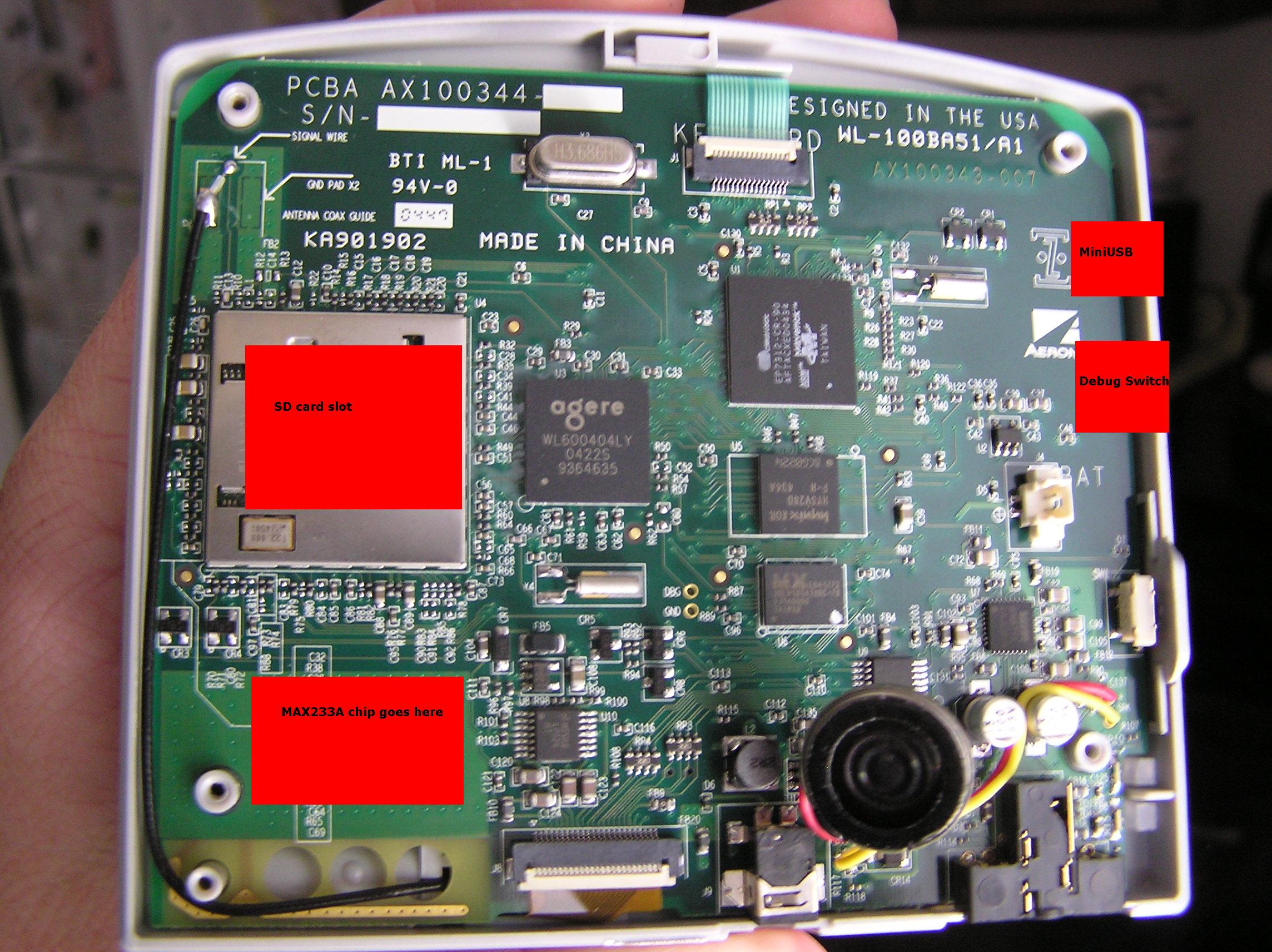


After the modifcation, the zipit runs a small version of Linux, and has a serial port that you can use for what you wish. The serial port connector is a type B mini-USB which fits easily in the allowed space.
The first step will be to take the MAX233A chip and glue it to the board, up-side-down in order to easily access the pins. Make sure you use a marker to mark which is pin 1 before you glue it down, otherwise it's easy to forget when you can't see the top of the chip. The first time I did this, I soldered all the wires onto the chip beforehand, but this was found to be far more difficult than just doing them one by one. A small drop of hot glue should be plenty, there isn't a lot stress on the chip.

Next up, go ahead and glue down the miniUSB connector and DIP switch. You'll also need to make a small cut in the side of the case so they will protrude slightly. Don't be afraid of using too much glue, you need a lot to hold the miniUSB connector down to the board while cables are being plugged and unplugged. It can also be removed easily enough if needed for some reason. Leave the SD card slot off for now, that will be installed after the serial port is tested. It's easier to debug if something goes wrong that way.
Now for the connections. The following is the pin to pin layout of what you'll need to solder. Note: the DIP version of the MAX233A does not have the same pinout!
| MAX233 | Connection | MAX233 | Connection |
|---|---|---|---|
| 1 | None | 11 | MAX233 Pin 16 |
| 2 | Txd2 Via | 12 | MAX233 Pin 15 |
| 3 | RxD2(R122) and RxD1(R121) | 13 | None |
| 4 | Pin 4 of miniUSB | 14 | None |
| 5 | Pin 2 of miniUSB | 15 | MAX233 Pin 12 |
| 6 | Ground | 16 | MAX233 Pin 11 |
| 7 | VCC | 17 | MAX233 Pin 10 |
| 8 | None | 18 | None |
| 9 | Ground | 19 | None |
| 10 | MAX233 Pin 17 | 20 | None |
Also, run a wire from ground and a wire from the debug pad to your DIP switch.
Tips:
Solder your wires to the MAX233 first, then cut them to the correct size and solder them to the bored. This way you won't knock the wires off the small resistors or pads while trying to do the connection on the chip.
The connections are often very delicate, put some hot glue blobs somewhere in the middle of the wires in order to keep them from moving around and breaking off.
You'll have to scrape off the insulation on top of the TxD2 via. An exacto knife should work well, but be gentle with it.
When soldering Rxd1 and Rxd2, be quick, else you may desolder both sides of the resistor by letting it heat up too much.


Once you're all done with that, you should be ready to build the cables and test it. You will need a miniUSB male to DB9 male cable, which will plug into the null modem for programming. The cable will need the following layout. Make note that the miniUSB connector looks like it has 5 pins, but in reality only 4 are used. The pinout for a USB is 1-2-3-x-4. The x most likely won't have a wire running in the cable that you get, and will be unused in this project.
| MiniUSB | DB9 |
|---|---|
| 2 | 2 |
| 3 | 3 |
| 4 | 3 |
| Shield | 5 |
This pinout avoids using pin 1 of the miniUSB, which is VCC on a stanard USB cable. This means you should, in theory, be able to plug a normal USB cable into your zipit, or this cable into a computer, and not destroy anything (I wouldn't recommend testing it). It's difficult to find male miniUSB to nothing cables, so I used a male miniUSB to male USB cable, and cut off the USB end (replacing it with a DB9).


Now, on to the first test! You'll need the upl program, a simple program to flash the zipit's chip, and the BURN3 firmware. The upl program for Linux can be found here zipit-flash-0.1.tar. You can also find the Windows version on the Internet, but I've had more luck with the Linux one (plus I usually run Linux). Just do a make/make install and follow the instructions in the README to launch the program with your correct serial port.
If all goes well and you manage to get the bootloader flashed and Linux running, you can move on to the SD/MMC card slot. The pinout is as follows,
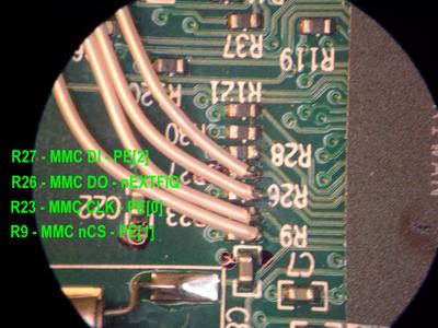
MMC pin-1 nCS <-- PE[1] (connect to R9)
MMC pin-2 DI <-- PE[2] (connect to R27)
MMC pin-5 CLK <-- PE[0] (connect to R23)
MMC pin-7 DO --> nEXTFIQ (connect to R26)

        9 \    Not used
         1|    /CS  -- PE1 -- R9 right side - 0V card selected
         2|    SO   -- PE2  --  R27 right side -- from CPU to card
         3|    GND  -- for power
         4|    +V 2.7-3.6V -- power
         5|    SCLK -- PE0 -- R23 right side -- serial clock
         6|    GMD  -- for card insert sense
         7|    SI   -- nEXTFIQ -- R26 right side - from card to CPU
         8|    Not used
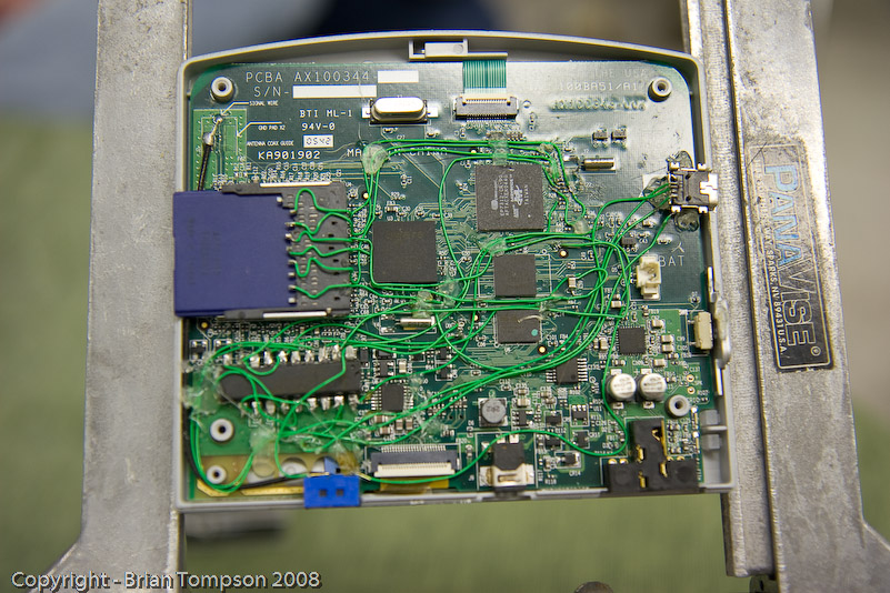
The most difficult part to solder will be the connections to the resistors due to the lack of space between them. Make sure you double check with a meter that none of the connections got accidentally soldered together before powering on. Also, it's best to clean any flux residue that may be between these resistors after to avoid any connections.
If all goes well, the finished product will look something like this.
Useful resources